A new era begins!
During the last couple of months, I’ve been designing and building the rocket destined for the next series of test flights that will pave the way to the future of my model rocketry efforts. A variation of the Artemis rocket design was chosen for these missions.
My initial choice was to build another X4 rocket for this purpose to be called “Vega”. After the results of Zephyr’s single deployment test flights, I decided to go a different route to cut the development cycle considerably, and go for the much simpler to build “Artemis” design. This allowed for more time to be spent developing the new technology.
The Artemis design was also picked as it is a design I am very familiar with, and have lots of flight data as it is the oldest / longest flying design in my fleet of rockets.
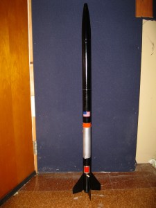
The new Artemis rocket is called “Pathfinder”. It’s name was chosen for the role it will play in my efforts to develop active electronic (computer) systems to control various events during the mission of a rocket flight. Pathfinder will also be the first of the Mid-Power rockets in my fleet to employ a full dual deployment recovery system.
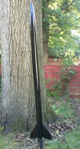
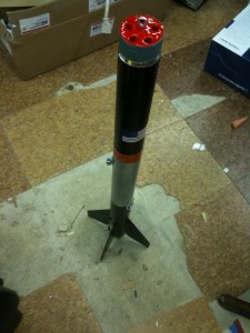
Artemis DD "Pathfinder" after the first coat of paint...
Pathfinder will fly its missions using a variation of the flight test configuration known as Artemis 1B (the test flight configuration that X2-01 “Big Red” used in April / March of 2010).
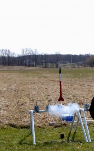
(Illustration 1) Artemis 1B takes to the skies for the second time
Beginning in October, and going through November, Pathfinder will fly a series of missions designed for me to “get the feel” for Dual Deployment flights, and to clear the path for the first flight of Perseus X6-01 (AKA, Perseus V) “Nesaru”, and my NAR Level 1 certification attempt.
About “Dual Deployment”
Dual deployment is a method used in high power rocketry where a smaller (drogue) parachute is deployed at apogee (peak altitude of the rocket’s trajectory). This parachute slows the rocket somewhat, but not slow enough to drift with the upper winds aloft. This is an important feature as high power rockets tend to reach apogee at a mile or more above ground level.
At a predefined lower altitude, the main parachute (a much larger one) is deployed to slow the rocket to a safe landing speed. All of this is accomplished with the use of electronics that monitor the altitude of the rocket during flight.
Dual deployment techniques allow for rockets to reach high altitudes, and still land somewhere close to the launch point.
While very common in high power rocketry, the use of this type of electronic systems is very rare for lower-mid power rockets such as the ones in my fleet. This is due to the complexityof the systems involved along with the limited space available in lower / mid power rocketry.
Challenges in design
The maximum body diameter of the Artemis rockets (and all of my others for that matter) is only 41.6 mm. Whatever techniques I employ has to be very small in size…and fairly lightweight.
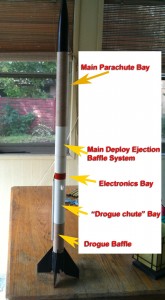
(Illustration 2) A breakdown of the components that make up the Artemis DD stack. This is a view before the rocket was painted. (Click image for a larger view.)
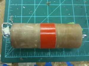
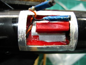
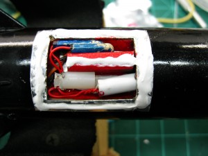
(Illustration 3) Electronics bay for Artemis Dual Deploy.
Typically, the electronic systems used in dual deployment rocketry employ the use of 9 volt batteries. I have deemed such batteries to be too much weight for class 1 rocketry. The Artemis DD makes use of the “A-23” 12 volt battery to power its systems. Small, and lightweight, it’s perfect for lighting the Quest G2 initiators used to deploy the parachutes.
One of the interesting aspects of this project for me is the fact that this is a VERY different way of thinking about model rocket design. No longer is the rocket a hollow tube with a nosecone, fins, and an engine. The “tube” is now a stack of “systems” each with a purpose, and each section is as complicated to engineer & build as one of my entire X4 or X5 rocket designs.
Illustration 2 (above) displays each of the sections of the Artemis Dual Deploy (DD) rocket stack.
Pathfinder features two ejection baffles in its design – one for the drogue chute, and the other for the main parachute.
The electronics bay was designed over a period of a few months before I came up with a miniaturized version of the bigger bays used in high power rocketry.
The altimeter used in Pathfinder is the Perfect Flite Stratologger.
The size of the stratologger JUST fits inside the BT-60 avionics bay.
Old computer type connectors are used for quick connect plugs to the igniters.
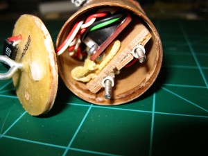
a tight fit inside the electronics bay!!
There is also a quick connect jack on the outside of the E-Bay switch ring for attaching to the external conduit that runs down the side of the booster to trigger the igniter that is behind the drogue ‘chute ejection baffle.
When the drogue chute is deployed, this connector becomes disconnected, allowing the two sections to separate. This concept was tested on Perseus Zephyr’s electronic (single) deploy test flights a couple of months ago.
That’s it for part 1. In part 2, I’ll unveil Artemis “Pathfinder” with its paint scheme, and share information about the ground testing!
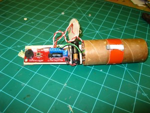
The Stratologger EXPOSED!
((( )))
